Why is a mould that is convex called a convex die and a mould that is concave called a concave die? The reason is that a set of moulds is divided into upper and lower moulds, depending on the way the moulds are installed, some upper moulds are convex and the lower moulds are concave.
In general, the convex die is the back die of the set (with an ejector pin) and the concave die is the front die.
The female mould, also known as the front mould, is also known as the fixed mould, and is the piece of the mould near the injection nozzle from the orientation of the injection moulding machine. The male mould, also known as the rear mould, is also known as the moving mould, which is mounted on the injection moulding machine and can be moved. To distinguish between male and female moulds individually, you have to look at whether there is an ejector hole or a glue inlet.
To really distinguish between convex and concave moulds, it depends on which side is used to define convex or concave.
The Function Of Convex Dies And Concave Dies
Both convex and concave dies are used for moulding, the concave die is usually the die base, which is placed under the product to be moulded to avoid movement of the product, the convex die is usually the upper touch, which is connected to the movement of the punch and other things to reduce the weight of the movement and to keep the direction of the striking force in line with the centre line of the mould. Of course, there are also convex moulds underneath and concave moulds on top.
The role of the convex and concave dies are the main parts of the stamping process. The die is machined into the required shape, and the plate to be processed on the press is punched through the die into the concave die hole, or leaked down, or topped out from the concave die. A desired part is then processed. The role of the convex and concave die plays two roles, one is that the hole is used as a concave die and the shape as a convex die. The simplest part is the washer, which is punched out at once, and it corresponds, of course, to have a convex die and a concave die on the opposite side. The convex die punches the hole and the concave die drops the shape. This is probably how people can distinguish between them.
In the process of mould design and production, we always encounter some small hole punching, generally speaking, we can produce stamping moulds as long as the strength of the punch is sufficient and is greater than 1.5 material thickness. However, special attention needs to be paid to the design of small hole punching dies and concave dies. Instead of discussing strength issues, here we will look at some of the common methods used to protect the die.
When it comes to small diameter punching, the impression is that the thickness of the material corresponding to a small diameter hole of φ1.0mm is generally less than 1.0mm. The reality is that for such a die, if the guiding accuracy is not sufficient, such a die can be very difficult to produce.
The Design of the cam die
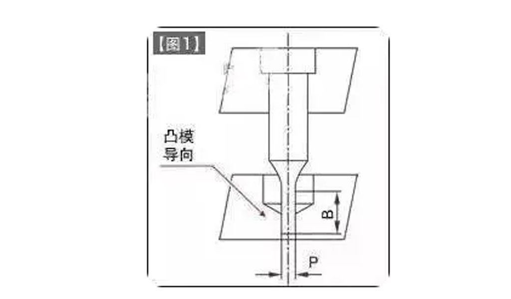
For protection, the punching die is shown in [Fig. 1] and a countermeasure to prevent breakage of the die is adopted by guiding the front end of the die through the unloading plate (die guide)

The relationship between P and B in the size of the die is based on a design criterion of B ≤ 10P.
In the case of small hole dies, as the B dimension becomes shorter, the die guidance becomes more difficult.
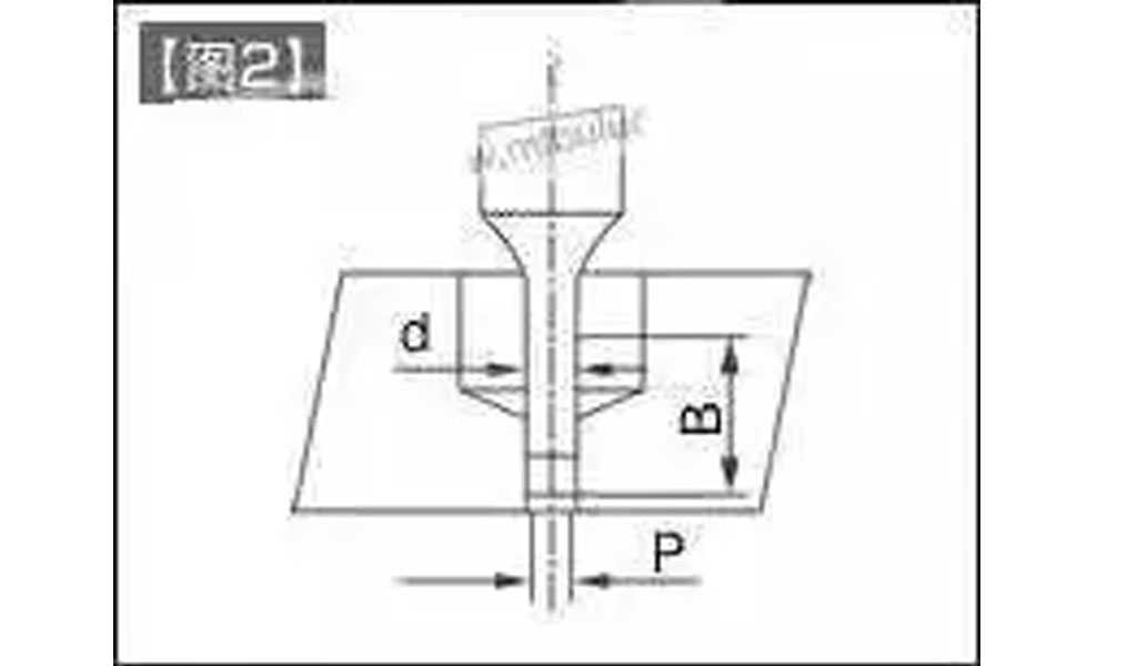
As a solution, a stepped convex die as shown in [Fig. 2] was used.

The d dimension on P is d ≤ P + 2t in order to prevent deformation inside the hole when the die is pulled out of the material.
The setting of the guide length at the front of the die: guide length ≥ die diameter.
In addition, the clearance between the die and the discharge plate hole is 0.003 or more on one side.
The design principle is based on the minimum clearance of 0.003 without oil film breakage.
Design of the concave die
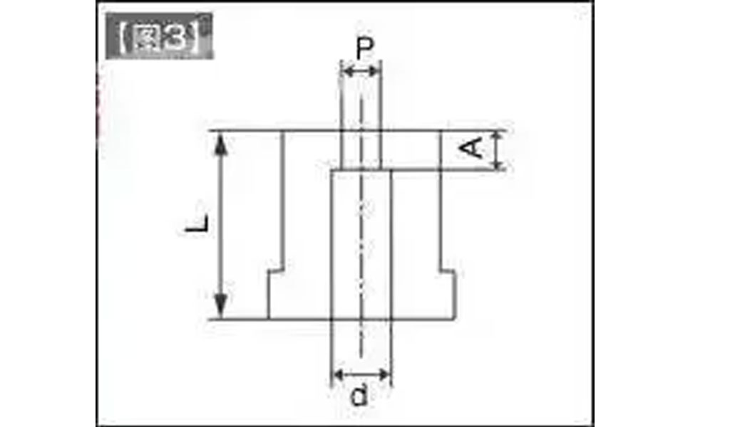
The main point in the design of a concave die is to avoid the accumulation of blanking waste in the hole of the die. The crux of the problem lies in the large drop force required and the large number of conflicting punching forces.

As a countermeasure, the edge length should be kept as short as possible (A). If possible, the design concept should be one piece at a time.
In principle, the drop hole (d”) should not be oversized in relation to the P”. At the same time, the length of the die (L) should also be reduced if the d” is reduced. Anti-clogging measures.
The mating gap should be greater than the normal gap to reduce the punching force.
In the case of small diameter holes, a conventional clearance will result in an elongated punching surface. This is also the reason for the accumulation of blanking waste in the die.
The most common problem in small hole punching is that the punching pin breaks easily. If the die is guided with high accuracy and the surface hardness of the material to be punched is not too high, I believe that the above method can be used to ensure that it is still very safe.

